|
|
|
Who's Online
There currently are 5981 guests online. |
|
Categories
|
|
Information
|
|
Featured Product
|
|
|
 |
|
|
There are currently no product reviews.
 ;
- Very good scan quality, PERFECT!
- Sehr gute scan Qualitaet, empfehlenswert!
Wolfgang Sundhaus
 ;
Good site, works ok and you get what you order, no problems experienced, got my manual within a day. A++++
;
Original well scanned manual. Got the job done. Microwave problem found & corrected. For $5 and a new magnitron from ebay, it was a cheap and good the first shot fix. Electrical schematics allowed me to mage sure every thing else was ok before cutting and order for parts. Hard to live without.
;
I was very skeptical of this website, I have never downloaded manuals before. I put it on the AMEX and payed through Paypal to ensure protection. I got the manual exactly as described and now I can replace the filter capacitor for this amp. Great Price, others selling for 12.99 or more and this is the same manual. I will search out this website for other manuals. Thank you
;
Manual was reasonably easy to follow. I am not an engineer or know much about electronics but with the manuals help I was able to figure out the problem, identify the part required for the repair. Replacement part cost around $30. Whilst replacing the part I was telling myself, "this aint gonna work cos it seems far too easy". Took about 15 minutes to do and my plasma TV works a treat. Would never have been able to do this without the service manual.
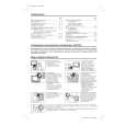
CONVERGENCE CRT CUT-OFF, BACKGROUND AND SUB-CONTRAST ADJUSTMENT
BGR ADJ. 2. Using the remote controller, call NORMAL mode. ADJUSTMENT NO VIDEO signal.
2
14A1-RU 14A2-RU
No. point Adjusting procedure/conditions Waveform and others
CONVERGENC Receive the "Crosshatch Pattern" signal. 1 CRT CUTOFF 1. Switch TV to VIDEO mode,BLUE BACK OFF, with ( To be done (I C BUS 2. Press R/C to set Picture Normal condition.
G adjustment. 1. Turn the 4-pole magnet to a proper opening anIC801.(TP851) R
3.0Vdc
after purity STATIC CONVERGENCE B CONTROL) 3. Connect the oscilloscope to Red OUT from
gle in order to superpose the blue and red colours. Range : 1 V/Div (DC)
RGB R
2. Turn the 6-pole magnet to a proper opening anFig. 5-1 Sweep : 5 msec/Div
0
gle in order to superpose the green colour over 1 V blue and red colours. 4. Adjust SCREEN VR ,so that the tip of signal reach 3.0 Vdc + 0.1 Vdc.
DYNAMIC CONVERGENCE G Adjust convergence on fringes of the B 2 SUB-BRIGHT1. Call " SUB-BRI" in service mode. (Receive CrossFig. 5-2 2 (I C BUS line 1, 2 and 3 have the same darkness
B
NESS hatch pattern with 5 black level windows) screen in the following steps. ADJUSMENT 2. Adjust SUB BRIGHT " bus data in order that a) Fig. 5-1: Drive the wedge at point "a" and swing the deflection coil upward.
b) Fig. 5-2: Drive the wedge at points "b" and "c" RGB CONTROL) wherelse is slightly brighter than line 1, 1 2 3 4 5
c) Fig. 5-3: Drive the "c" wedge deeper and swing R line 4. 1, 2, 3 are in same black level.
swing deflection coil downward. 3 and finally line 5 will be the brighter than G
the deflection coil rightward.
d) Fig. 5-4: Drive the "b" wedge deeper and swing 3 WHITE BAL1. Receive the "Monoscope Pattern" signal. Refer to Page 6.
2. Fix all wedges on the CRT and apply glass Fig. 5-3 ICE MODE 3. Connect DC miliammeter between the TP 602 Y : 0.310 3. Apply lacquer to the deflection yoke lock screw, G 7500°K ( white ). DOWN by volume key.
R
the deflection coil leftward. ANCE SERV2. Press R/C to set Picture NORMAL condition. # 7500° K X : 0.300
tape over them. BGR ADJ. (I2C BUS ) TP 603 ( + ).
CONTROL) 4. Check Beam current should be around 800µA) ( MINOLTA COLOUR ANALYZER
magnet unit (purity, 4-pole, 6-pole magnets) and B 5. Set it to service mode and adjust the DRI-GS, & CA-100) magnet unit lock screw. DRI-BS data to have a colour temperature of *NOTE: Above DATA can be UP/
8
Wedge "a" LUMINATE Y signal. 20"/21" 10cd/m2 120cd/m2
Finally received the Red-only and Blue-only sig6. Receive "WHITE" pattern, WITH BURST signal, nals to make sure there is no other colours on the Fig. 5-4 and set BRIGHTNESS Y by generator, to ** 10 LOW HIGH screen. cd/m2 (MINOLTA CA-100) by reducing 14" 10cd/m2 200cd/m2 7. Adjust "CUT-R" & "CUT-G" to get 7,500. Then go
back NORMAL mode (HIGH BRIGHT**) to check * 7500° K About
100° colour temperature. If out of range, back to (1). DRI-GW="DRI-GS"DATA-5
DRI-BW="DRI-BS" DATA-5
Lacquer Note: This adjustment must be done after Wedge "b" "c"
warming up the unit for 30 minutes or longer with a beam current over 500µA. * ADJUST DRI-GC/GW, DRI-BC/BW as following DATA, after finishing DRI-BS and DRI-GS DATA ADJUSTMENT.
6-pole magnet DRI-BW="DRI-BS"-7*DRI-RC=25*, DRI-
4-pole magnet DRI-RW=32 (FIXED), DRI-GW="DRI-GS"-7*,
BC="DRI-BS", DRI-GC="DRI-GS"-7* CRT neck 4 Maximum 1. Receive the "Monoscope Pattern" signal. beam check 2. Press R/C to set Picture NORMAL condition.
Purity magnet (Full Scale: 3 mA Range) Lacquer 40cm and TP602 (�).
3. Connect the DC miliammeter between TP603 (+) 4. Beam current must be within 800 ± 100 µA.
8-1 8-2
 $4.99 14A1RU SHARP
Owner's Manual Complete owner's manual in digital format. The manual will be available for download as PDF file aft…
|
|
|
> |
|