|
|
|
Who's Online
There currently are 5727 guests online. |
|
Categories
|
|
Information
|
|
Featured Product
|
|
|
 |
|
|
There are currently no product reviews.
 ;
Well.. I'd searched for this manual and although I found many copies online I was pleased to find your website with a well balanced pricing system and easy to search and follow links. That together with the very quick response time was just what I was looking for.. being a very impatient tech.. ;-) I had the service manual in front of me within a short time.
Bookmarked.. and you can bet I will always come here first for my service & user manuals..
best regards
Ed(Tony) Foley
G7WHK
;
I will definitely be back for more information when I need it.
;
The service manual when downloaded and printed out was clear and easy to read. I would have liked to have been able to enlarge some details, but this was not possible as the file permissions did not allow this. The service was very good. The time taken from placing my order to downloading the document was only a few minutes.
 ;
The manual is useful for trouble shooting for an old instrument. It saved money,and let me enjoy DIY.
;
Perfect source of information for replacing the HDD and performing general diagnostics.
ADJUSTMENT PRECAUTION: PURITY ADJUSTMENT Make sure TV Set is in "Normal Condition" before switch to service mode for adjustNo. point Adjusting procedure/conditions Waveform and others ment.
1 PURITY ADJ. 1. Receive GREEN-ONLY signal. Adjust the beam current to about 500 µA. 2. Degauss CRT enough with the degausing coil.
a b
Note: Follow the Job Instruction Sheet to adjust the magnetic field. 3. Maintain purity magnet at the zero magnetic field and keep the static convergence roughly 1 Tuner IFT 1. Get tuner ready to receive the CH. E 9 adjusted. ( PRESET ) signal,but with no signal input. rank A requirements. the tuner antenna. ( RF SWEEP )
100k 75ohm
PIF ADJUSTMENT
No. point Adjusting procedure/conditions Waveform and others
2. Connect the sweep generator's output cable to 10k 1n60 1000p through microscope. Adjust landing to the
Oscilloscope IF OUT
Adjust the PLL data. 4. Observe the points a, b as shown in Fig. 4-1 Fig. 4-1 5. Orient the raster rotation to 0 eastward. 6. Tighten up the deflection coil screws. 3. Adjust the sweep generator's to 80dBuV. 4. Connect the response lead ( use LOW IMPED-
ANCE probe with wave detector ; see Fig.1 ) to » Tightening torque: 108 20 N (11 ± 2 kgf) A the tuner's IF output terminal. ( This terminal Fig.1 7. Make sure CRT corners landing meet the A rank requirements. If not, stick the magnet sheet must have the probe alone connected ). to correct it. 5. Set the RF AGC to 0 6 V no saturation with B Note: This adjustment must be done after the waveform. longer with a beam current over 500 µA. shown in Fig. 2. -1.5+/-0.8dB Fig.2 * For the following colours press R/C RGB key to Note: Be sure to keep the tuner cover in position Fig. 4-2
E-9 CH
6. Adjust tuner IF coil to obtain the waveform as A = B
P C warming up the unit for 30 minutes or
during this adjustment. change. Rank "A"
(on right of the CRT)
Green-only Blue-only Red-only
2 RF-AGC 1. Receive "PAL COLOUR BAR" signal. Note: For the 50 ohm signal
TAKE OVER » Signal Strength: 57 ± 1 dBµV (75 ohm open) strength gauge, when not POINT AD2. Connect the oscilloscope to TP201(Tuner�s AGC u s g 0 / 7 5 i m p d a n c e
7
7-1 7-2
(I C BUS 52±1dBµV(75 ohm open), in-2 CONTROL) Oscilloscope stead of 57±1dBµV (75 ohm
A Signal-colour screen cleared
JUSTMENT Terminal) as shown in Fig. 3. adapter, signal strength is
B + TP210 open).
0.1V Precaution: The loss of using
� impedance adapter A = B Fig. 4-3
Rank "A" �
Bias box TV Set
+
» Bias box: About 4.5 V (on left of the CRT)
Fig. 3 * Press R/C RGB key for 1 sec-
3. Call "AGC" mode in service mode. Adjust the ond in NORMAL MODE, the
"AGC" bus data to obtain the Tuner output pin colour will change to RGB mono drop 0.1V below maximum voltage. colour mode.
4. Change the antenna input signal to 63~67dBµV,
and make sure there is no noise. The TEXT "R. G. Cy" Key
5. Turn up the input signal 90~95 dBµV to be sure can be directly use to change
that there is no cross modulation beat. to other colours screen.
14D1-S/G/W 14D2-S/G
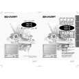 $4.99 14D1S SHARP
Owner's Manual Complete owner's manual in digital format. The manual will be available for download as PDF file aft…
|
|
|
> |
|