|
|
|
Who's Online
There currently are 6036 guests online. |
|
Categories
|
|
Information
|
|
Featured Product
|
|
|
 |
|
|
There are currently no product reviews.
 ;
again you did a very good job. It was fast too. Photocopy are really readable and clear
 ;
Probably it never existed a 1081 official service manual from Commodore, it's look more like a NAPCEC service manual & diagrams compilation of the 1084 series and his variants, like the nap6523, 8cm505, 1084S, 1084P and obviously the 1081. It's more complete than other scans and the quality of the scans also are far superior. It has two circuit diagrams variants of the 1081, mono and stereo versions. It doesn't include a diagram for the Philips CM8500 or CM8501, they look like the 1081 but they are slightly different.
;
Rapid, clear well done as all the scheme I downloaded from this site. Great job very functional and very useful
;
Great copy of the manual, has all information required for servicing,
;
I work at an authorized service center and I can tell if a manual is as it should be. This one is. It may be a scan, but a very good one at that. The interesting part for me was the curcuit diagram which was scanned at high quality, making it as good as the original. I will definitely be back as a customer. I need not say this, but I will: the price was the best. Thank you owner-manuals.com .
32L-S400, 36L-S400 CL32S40, CL36S40
IMPORTANT SERVICE SAFETY PRECAUTION
(Continued) BEFORE RETURNING THE RECEIVER (Fire & Shock Hazard)
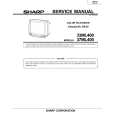
Before returning the receiver to the user, perform the following safety checks. 1. Inspect all lead dress to make certain that leads are not pinched or that hardware is not lodged between the chassis and other metal parts in the receiver. 2. Inspect all protective devices such as non-metallic control knobs, insulating materials, cabinet backs, adjustment and compartment covers or shields, isolation resistor-capacity networks, mechanical insulators, etc. 3. To be sure that no shock hazard exists, check for leakage current in the following manner. � Plug the AC cord directly into a 120 volt AC outlet, (Do not use an isolation transformer for this test). � Using two clip leads, connect a 1.5k ohm, 10 watt resistor paralleled by a 0.15µF capacitor in series with all exposed metal cabinet parts and a known earth ground, such as electrical conduit or electrical ground connected to earth ground. � Use an AC voltmeter having with 5000 ohm per volt, or higher, sensitivity to measure the AC voltage drop across the resistor. � Connect the resistor connection to all exposed metal parts having a return to the chassis (antenna, metal cabinet, screw heads, knobs and control shafts, escutcheon and etc.) and measure the AC voltage drop across the resistor. AII checks must be repeated with the AC ine cord plug connection reversed. (If necessary, a nonpolarized adapter plug must be used only for the purpose of completing these check.) Any current measured must not exceed 0.5 milliamp. Any measurements not within the limits outlined above indicate of a potential shock hazard and corrective action must be taken before returning the instrument to the customer.
1.5k ohm 10W
0.15µF TEST PROBE
TO EXPOSED METAL PARTS
CONNECT TO KNOWN EARTH GROUND
21210987654321098765432109876543212109876543210987654321098765432121098765432109876543210987654321 21210987654321098765432109876543212109876543210987654321098765432121098765432109876543210987654321 21210987654321098765432109876543212109876543210987654321098765432121098765432109876543210987654321
SAFETY NOTICE
Many electrical and mechanical parts in television receivers have special safety-related characteristics. These characteristics are often not evident from visual inspection, nor can protection afforded by them be necessarily increased by using replacement components rated for higher voltage, wattage, etc. Replacement parts which have these special safety characteristics are identified in this manual; electrical components having such features are identified by "Ã¥" and shaded areas in the Replacement Parts Lists and Schematic Diagrams. For continued protection, replacement parts must be identical to those used in the original circuit. The use of substitute replacement parts which do not have the same safety characteristics as the factory recommended replacement parts shown in this service manual, may create shock, fire, X-radiation or other hazards.
21210987654321098765432109876543212109876543210987654321098765432121098765432109876543210987654321 21210987654321098765432109876543212109876543210987654321098765432121098765432109876543210987654321 21210987654321098765432109876543212109876543210987654321098765432121098765432109876543210987654321
3
|
|
|
> |
|