|
|
|
Who's Online
There currently are 6043 guests online. |
|
Categories
|
|
Information
|
|
Featured Product
|
|
|
 |
|
|
There are currently no product reviews.
 ;
Good quality (clearly readable) manual, I'm glad I could find it here, at a bargain price!
;
Speedy transaction with a quick download. Awesome hassle-free service.
;
very poolite and healpful secure transaction thanks allot
;
- Very good scan quality, PERFECT!
- Sehr gute scan Qualitaet, empfehlenswert!
Wolfgang Sundhaus
 ;
Good site, works ok and you get what you order, no problems experienced, got my manual within a day. A++++
The control circuit is subject to negative feedback from the secondary side as shown in fig (4). A photo coupler (PC002) is employed to insulate between the primary side and the secondary side to feed back the control signal to the primary side. When the output voltage is increased by energy transmission from T001, the voltage detected by R109 and R111 is compared with the reference voltage of IC102. When it exceeds the reference voltage, the current flowing through IC102 (that is, the photo diode current of PC002) is increased and transmitted to the primary side. Then the potential at the feedback pin (2 pin) of IC102 is decreased to control Q001. Therefore, the change in the output voltage on the secondary side is passed through IC102 and PC002 to control Q001, stabilizing the output voltage.
(4) Overcurrent protection circuit (Primary side)
The inverter circuit of the primary side is connected with the current detection resistor R012. When an overcurrent occurs in the secondary side, the current flowing through the primary side inverter Q001 is increased. The current is detected by R012, and passed through R013 to IC002 overcurrent restricting pin (3 pin) to turn OFF Q002, shutting off all power. To resupply the power, turn off and on the power. Refer to fig (4).
(5) Rectifying/smoothing circuit (+5V)
fig (6) Rectifying/smoothing circuit The high frequency pulse generated by the inverter circuit is decreased by the converter transformer, rectified by the high frequency diode D103, and smoothed by C103 and C104.
fig (7) +5V rectifying/smoothing circuit voltage waveform
AR-M205 ELECTRICAL SECTION 13-4
 $4.99 ARM205 SHARP
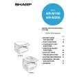
Owner's Manual Complete owner's manual in digital format. The manual will be available for download as PDF file aft…  $4.99 ARM205 SHARP
Parts Catalog Parts Catalog only. It's available in PDF format. Useful, if Your equipment is broken and You need t…
|
|
|
> |
|