|
|
|
Who's Online
There currently are 5885 guests and
2 members online. |
|
Categories
|
|
Information
|
|
Featured Product
|
|
|
 |
|
|
There are currently no product reviews.
 ;
Very good manual. Plenty of service information including alignment instructions. Clear circuit diagram. Excellent, thank you.
 ;
Good morning, the service manual you sent me was perfect.
Your service and answering are excellent.
I recomend this service.
Best regards.
;
I had been looking everywhere for a proper service manual for this VCR. Everywhere else that has this available for download has a very light version. This is the full service manual with all aspects that would interest anyone looking for the service manual for the AIWA HV-MX100 Worldwide VHS VCR. Great quality (as always). A winner hands down. Best Quality.
;
Top quality manual. Covers all aspects you'd expect in a top quality service manual for this Panasonic VHS VCR. The manual resolution is high. Another top quality manual from the only site worth downloading manuals from! If you're looking for a manual for the PV-9662 VHS VCR, this is the one you'll want to get!
;
complete part-lists and pcb layout, schematic diagram is good enlargable,
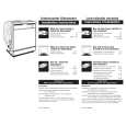
AR-405 * Note for assembling the copy lamp unit Move the copy lamp unit to the paper exit side, and fix the copy lamp unit wiht the harness guide so that the distance between the copy lamp harness and the lower frame is about 25 ~ 30 mm with the copy lamp harness extended. Shift the copy lamp unit to the paper exit side, and fix it with the harness guide so that the distance from the lower frame is about 24 ± 2mm with the copy lamp harness extended. After fixing, manually shift the copy lamp unit a few times to check that it moves smoothly. If the copy lamp harness is loosely fixed, the copy lamp unit may jump up when reading, resulting in abnormal reading. AR-2XX/3XX series
(2) Vertical image distortion balance adjustment (No. 2/3 mirror base unit installing position adjustment)
This adjustment is to adjust the parallelism of the mirror base to the OPC drum surface and the original surface. 1) Manually turn the mirror base drive pulley to bring mirror base B into contact with mirror base positioning plate. If, at that time, the front frame side and the frame side of mirror base B are brought into contact with the mirror base positioning plate simultaneously, the parallelism is correct and there is no need for adjustment.
24±2mm
AR-405
(3) Sub scanning direction distortion adjustment (Winding pulley position adjustment)
This adjustment is executed in the following cases:
25±30mm
� � �
When the mirror base drive wire is replaced. When the lamp unit, or No. 2/3 mirror holder is replaced. When a copy shown below is made.
La Lb
Paper exit direction Original Copy
1/21/1999
7�8
|
|
|
> |
|