|
|
|
Who's Online
There currently are 5846 guests online. |
|
Categories
|
|
Information
|
|
Featured Product
|
|
|
 |
|
|
There are currently no product reviews.
 ;
Print was clear and easy to read. Thank you Joe joeoldaudio
;
Very great deal. In a few minutes a have the manual, that I needed. Thanl you very much
;
Manual was complete. Received it quickly. No problems
;
Product was very good. Received quickly and complete
 ;
The Sony AV-3600 service manual was what I needed for the repair of this unit
Thanks for the good service
Dave
CD-C1831V
CP-C1831
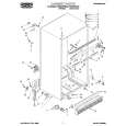
STEP REMOVAL 1 Front Speaker PROCEDURE FIGURE 1. Front Panel ............ (A1) x1 9-1 2. Tip .......................... (A2) x2 3. Screw ..................... (A3) x6
CP-C1831
(A3)x2 Tweeter ø3x10mm (A3)x4 ø4x12mm
(A2)x2
Note: The Surround speakers can be easily disassembled. Therefore the disassembling method is not described. For details refer to the disassembling drawing in the Parts Guide.
Woofer
Front Panel (A1)x1 Screw Driver
Figure 9-1
REMOVING AND REINSTALLING THE MAIN PARTS
CD MECHANISM SECTION
Perform steps 1, 2, 3, 11, 12, 13, 14 and 15 of the disassembly method to remove the CD mechanism.
Loading Motor Motor PWB
How to remove the loading motor (See Fig. 9-2)
1. Remove the screws (A1) x 2 pcs., to remove the loading motor.
(A1) x2 ø2.6 x5mm
How to remove the pickup (See Fig. 9-3)
1. Remove the screws (B1) x 2 pcs., to remove the shaft (B2). 2. Remove the stop washer (B3) x 1 pc., to remove the gear (B4). 3. Remove the pickup. Note After removing the connector for the optical pickup from the connector, wrap the conductive aluminium foil around the front end of connector to protect the optical pickup from electrostatic damage. Figure 9-2
(B1) x2 ø2.6x6mm
Stop Washer (B3)x1 Pickup
Shaft (B2) x1
CD Mechanism Gear (B4) x1
Figure 9-3
�9�
|
|
|
> |
|