|
|
|
Who's Online
There currently are 5940 guests online. |
|
Categories
|
|
Information
|
|
Featured Product
|
|
|
 |
|
|
There are currently no product reviews.
 ;
Nice manual. Clear copy and very rare, to boot. Great price, too!
 ;
Excellent service manual. Complete service info. with schematics, step-by-step instructions and illustrations. Well worth the price!
;
Great product, helped me to restore vintage walkman cassette.
Just some pictures could be little bit more sharp and contrast
Thank you
;
I love older radio's and the service manuals that are sometimes hard to find. Was able to find a manual quite easily on this site.
;
Thank you for your shop manual! Your help was very useful - the device is repaired! Once again - Thank you! I wish you a successful business! Edward (Russia).
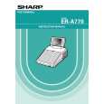
8. Removing and replacing the LCD unit
1) Remove the four fixing screws cabinet . of the display unit from the top
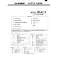
9. Expansion RAM Board : UP-P02MB2
Make sure to save data before installing this option 1) Remove the top cabinet. 2) Install the Expansion RAM Board on the Main PWB. to the Option RAM connector
2
a) Insert the Expansion RAM Board aslant into the option RAM connector. b) Push the RAM disk unit Expansion RAM Board is locked by the arms of option RAM connector. It is possible to install one UP-P02MB2. Be careful of the direction of Expansion RAM Board to be installed. Install the Expansion RAM Board with the notch part of the PWB (Figure A) come right. Installing the Expansion RAM Board in the wrong direction may damage the connector part or make the machine out of order.
3
A 1
3
1
Fig. 5 2) Remove the two fixing screws unit. of the LCD unit in the display
3) The LCD unit is assembled with seven pawls. Remove the pawls in the order of to as shown in the figure.
LCD cabinet hear side
c
d
e
b
f
Fig. 7 3) Removing the Expansion RAM Board. a) Open the arms of option RAM connector right and left. b) The Expansion RAM Board will be lifted automatically.
a
g
10. RS232 I/F: ER-A7RS & EFT I/F: ER-02EF
4
1) Remove the rear cover. 2) Remove the two screws Fig. 6 3) Insert the I/F PWB from the shassis.
to the connector. .
4) Fix the I/F bracket to the shassis with screws 5) Install the ferrite core 6) Install the Nylon band . to the cables.
 $4.99 ER-A770 SHARP
Parts Catalog Parts Catalog only. It's available in PDF format. Useful, if Your equipment is broken and You need t…
|
|
|
> |
|