|
|
|
Who's Online
There currently are 6015 guests and
2 members online. |
|
Categories
|
|
Information
|
|
Featured Product
|
|
|
 |
|
|
There are currently no product reviews.
 ;
Very good conversation, Pretty fast Service, wood do it again,
Have paid by Paypal, so i got the Service Manual online after 15 Min.
Very helpfully.
Greeting from Germany,
Hans
;
Good-quality scans. Detailed description. I hope I can repair the machine.
;
High-quality scanning. Detailed description. Recommend for all technician. A+++
;
This is a good quality scan of the original Service Manual from Nordmende, Germany. Contains the circuit diagram, PCB layout, adjust/tune instructions as well. It is NOT in English but in GERMAN language! That was quite right for my german friend from the lower east side in Berlin.
 ;
Received via e-mail this PDF manual is worth the money. This is a quality scan of a manual in excellent condition and is just as good as having the original manual in hand. I have later seen the original manual and it was printed in colour, but this particular manual is black & white but scan resolution is high end quality! All drawings and pictures are presented in great detail. So, nearly perfect score in my opinion.
If you own the turntable you also should own the manual!
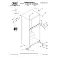
LC-15B5H
12. Remove the two lock screws from the inverter PWB, and detach the inverter PWB. 13. Remove the one lock screw from the card frame cover over, and detach the card frame cover. 14. Remove the five lock screws from the main PWB, and undo the claw a. Detach the main PWB by lifting the area around the claws and pulling the PWB out. 15. Remove the five lock screws from the analog PWB, and undo the claws b and c. Detach the chassis frame (right) from the analog PWB by pulling out the terminals. In the same way, undo the claws d and e, and detach the chassis frame (left) from the analog PWB by pulling out the terminals. Note: When detaching the main PWB and analog PWB, be careful not to break the PWB-fixing claws. 16. Remove the one lock screw from the card LED PWB, and detach the card LED PWB. 17. Remove the four lock screws from the LCD panel unit, and detach the LCD panel unit.
15 15 13 14
Main PWB Analog PWB
14
a
d
Chassis Frame (L) b Card Frame Cover
12
16
c Chassis Frame (R)
e
Card LED PWB Inverter PWB
17
10
|
|
|
> |
|