|
|
|
Who's Online
There currently are 5975 guests and
2 members online. |
|
Categories
|
|
Information
|
|
Featured Product
|
|
|
 |
|
|
There are currently no product reviews.
 ;
Good product and very helpfull to repair. Many thanks.
;
Very good product. Best service manual. Many thanks
;
I am only search for 5 Minute, by it in 5 Minutes to and get ist in few ours! Best i found in the Internet and my Amplifer is repaired as well! Thank you
 ;
Readable text and good copy. Very much needed if you wish to do some repairs on this fine old unit.
;
Fint forløb med levering af manualen. Kvaliteten af skanningen betegnes som middel
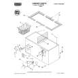
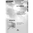
LC-20B5E
14. Remove the two lock screws from the inverter PWB, and detach the inverter PWB. 15. Remove the five lock screws from the main PWB, and undo the claws a and b. Detach the main PWB by lifting the area around the claws and pulling the PWB out. 16. Remove the one lock screw from the card frame cover over, and detach the card frame cover. 17. Remove the two lock screws from the 21-pin terminal. 18. Remove the four lock screws from the analog PWB, and undo the claws c and d. Detach the chassis frame (right) from the analog PWB by pulling out the terminals. In the same way, undo the claws e and f, and detach the chassis frame (left) from the analog PWB by pulling out the terminals. Note: When detaching the main PWB and analog PWB, be careful not to break the PWB-fixing claws. 19. Remove the one lock screw from the card LED PWB, and detach the card LED PWB.
18
15
Main PWB
15
16
Chassis Frame (L) a Analog PWB e
17 14
Card Frame Cover
b
c d
19
f
Chassis Frame (R)
Card LED PWB
Inverter PWB
10
|
|
|
> |
|