Gut, sehr gut! It helps me much! I couldn't find this schema nowhere. Good quality
Text excerpt from page 1 (click to view)
DESCRIPTION OF SCHEMATIC DIAGRAM
SCHEMATIC DIAGRAM
VOLTAGE MEASUREMENT CONDITION:
1. The voltages at test points are measured on the stable supply voltage of AC 220-240V. Signals are fed by a colour bar signal generator for servicing purpose and the above voltages are measured with a 20k ohm/V tester.
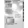
Models
LC-26P50E LC-32P50E LC-37P50E
INDICATION OF RESISTOR & CAPACITOR:
RESISTOR 1. The unit of resistance "�" is omitted. (K=k�=1000 �, M=M�). 2. All resistors are ± 5%, unless otherwise noted. (K= ± 10%, F= ± 1%, D= ± 0.5%) 3. All resistors are 1/16W, unless otherwise noted. CAPACITOR 1. All capacitors are µF, unless otherwise noted. (P=pF=µµF). 2. All capacitors are 50V, unless otherwise noted. CAUTION:
This circuit diagram is original one, therefore there may be a slight difference from yours.
SAFETY NOTES:
1. DISCONNECT THE AC PLUG FROM THE AC OUTLET BEFORE REPLACING PARTS. 2. SEMICONDUCTOR HEAT SINKS SHOULD BE REGARDED AS POTENTIAL SHOCK HAZARDS WHEN THE CHASSIS IS OPERATING.
CONTENTS
Page DESCRIPTION OF SCHEMATIC DIAGRAM �������������������� D2 AV Unit ��������������������������������� D3 � D10 KEY Unit ��������������������������������D11 � D12 MAIN Unit ��������������������������������D13 � D32 POWER Unit �������������������������������D33 � D34 INVERTER Unit (LC-26P50E) �����������������������D35 � D36 INVERTER Unit (LC-32P50E) �����������������������D37 � D38 INVERTER Unit (LC-37P50E) �����������������������D39 � D40 R/C, LED Unit ��������������������������������� D41
IMPORTANT SAFETY NOTICE:
PARTS MARKED WITH " " ( ) ARE IMPORTANT FOR MAINTAINING THE SAFETY OF THE SET. BE SURE TO REPLACE THESE PARTS WITH SPECIFIED ONES FOR MAINTAINING THE SAFETY AND PERFORMANCE OF THE SET.