|
|
|
Who's Online
There currently are 5970 guests online. |
|
Categories
|
|
Information
|
|
Featured Product
|
|
|
 |
|
|
There are currently no product reviews.
 ;
nice completed SERVICE MANUAL as the description THANK YOU !!!-
;
Hard to find service manual describing the PLL circuit of the AKAI AP-306.
Thanks to have it available.
;
Gut, sehr gut! It helps me much! I couldn't find this schema nowhere. Good quality
DESCRIPTION OF SCHEMATIC DIAGRAM
VOLTAGE MEASUREMENT CONDITION:
1. When the exclusive-use AC adapter is used, the colour bar signal of colour bar generator for service is input to get the normal screen. When the audio is minimized, the voltage value is measured with the 20 k�/V tester.
SCHEMATIC DIAGRAM
WAVEFORM MEASUREMENT CONDITION:
1. When the exclusive-use AC adapter is used, the colour density, lightness and colour hue are set to the center position, and the signal of colour bar generator for service is observed to get waveform.
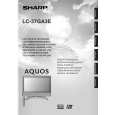
Models Models
LC-32GA3E LC-37GA3E
INDICATION OF RESISTOR & CAPACITOR:
RESISTOR 1. The unit of resistance ��� is omitted. (K=k�=1000 �, M=M�). 2. All resistors are ± 5%, unless otherwise noted. (J= ± 5%, F= ± 1%, D= ± 0.5%) 3. All resistors are Carbon type, unless otherwise noted. C : Solid W : Cement S : Oxide Film T : Special N : Metal Coating CAPACITOR 1. All capacitors are mF, unless otherwise noted. (P=pF=mmF). 2. All capacitors are Ceramic type, unless otherwise noted. (ML) : Mylar (TA) : Tantalum (PF) : Polypro Film (ST) : Styrol
CAUTION:
This circuit diagram is original one, therefore there may be a slight difference from yours.
IMPORTANT SAFETY NOTICE:
PARTS MARKED WITH �å� ( )ARE IMPORTANT FOR MAINTAINING THE SAFETY OF THE SET. BE SURE TO REPLACE THESE PARTS WITH SPECIFIED ONES FOR MAINTAINING THE SAFETY AND PERFORMANCE OF THE SET.
SHARP CORPORATION
|
|
|
> |
|