|
|
|
Who's Online
There currently are 6043 guests online. |
|
Categories
|
|
Information
|
|
Featured Product
|
|
|
 |
|
|
There are currently no product reviews.
 ;
El producto satisface las necesidades del servicio t
;
This is a good quality scan of the Operation & Maintenance (Service) Manual for the PAL version of this high-band broadcast umatic, BVU-800P
All schematics and lineup procedures appear to be included in this one manual AFAICT.
The file size is just over 113 MB which gives an idea of the quality and number of pages.
All of the schematics, which contain some fairly small print, are easily readable when you zoom into the page.
John Thompson, Newcastle Upon Tyne, England.
;
Good quality, all schematics of few of models. There is also short form of user manual and regulation manual.
;
Perfect copy of the service manual. you can enlarge every page, and it comes up
with all details.
;
It´s very very nice manual with all, what i need. Original in good quality. Very fast business. Very much thanks...
R-2275 R-2285
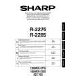
HOW TO RELEASE THE POSITIVE LOCK® CONNECTOR.
Terminal
Procedure 1. Pushing the lever of positive lock® conductor. 2. Pull down the connector from the terminal. 3. Now, the connector is free. Note: If the positive lock ® has a insulation sleeve, first remove it. If you do not so, you can not push the lever of positive lock ®. CAUTION: THE POSITIVE LOCK® TERMINAL CAN NOT BE DISCONNECTED BY ONLY PULLING. BECAUSE ONCE YOU (SERVICE PERSONAL) HAVE CONNECTED THE POSITIVE LOCK® CONNECTOR TO THE TERMINAL, THE POSITIVE LOCK® CONNECTOR HAS BEEN LOCKED.
Positive lock® connector 1 Push Lever
2 Pull down
Figure C-6. How to release the positive lock connector.
EXHAUST COVERS A AND B REMOVAL
(Exhaust cover A) 1. Remove the single (1) special screw holding the exhaust cover A to the rear cabinet, using the special driver LHSTIX DLR4-100T. 2. Release the tab of the exhaust cover A from the hole of the rear cabinet, and remove the exhaust cover A. 3. Now, the exhaust cover A is free. (Exhaust cover B) 1. Remove the single (1) special screw holding the exhaust cover B to the rear cabinet, using the special driver LHSTIX DLR4-100T). 2. Release the tab of the exhaust cover B from the hole of the rear cabinet, and remove the exhaust cover B. 3. Now, the exhaust cover A is free.
SCREW DRIVER TYPE: LHSTIX DLR4-100T
SPECIAL SCREW
NOTE: When securing or loosening the special screw, LHSTIX DLR4-100T TYPE screw driver should be used.
26
 $4.99 R2275 SHARP
Owner's Manual Complete owner's manual in digital format. The manual will be available for download as PDF file aft…
|
|
|
> |
|