|
|
|
Who's Online
There currently are 5801 guests online. |
|
Categories
|
|
Information
|
|
Featured Product
|
|
|
 |
|
|
There are currently no product reviews.
 ;
Manual found fast and good quality, very helpfull service
;
8-17-12 Been using the sight for about 6 months. Fast Downloads and top quality
Manuels !
 ;
Everything was great, the manual, the response time, the simplicity of the order, and the
Price. The only thing that I could possible say on a negative note would be that the manual I ordered was more for a service tech. There were a lot of schematic diagrams that didn't help me solve the problem. However I would order again and recommend the web sight to others.
;
I'd been looking for this manual for awhile. Exactly what I needed - and at an excellant price. Thanks!
;
very complete. acceptable resolution. details are a little unclear. is a manual note 8.
COMPONENT REPLACEMENT AND ADJUSTMENT
MAGNETRON REMOVAL
1. CARRY OUT 3D CHECKS. 2. Remove the two (2) screw holding the chassis support to the oven cavity and the magnetron. 3. Disconnect the H.V. wire B and filament lead of the transformer from the magnetron. 4. Release the chassis support from the oven cavity. 5. Move the air intake duct to left. 6. Remove the air deflector A from the magnetron. 7. Carefully remove two (2) screws holding magnetron to waveguide, when removing the screws hold the magnetron to prevent it from falling. 8. Remove the magnetron from the waveguide with care so the magnetron antenna is not hit by any metal object around the antenna. 9. Remove the magnetron cushion from the magnetron. CAUTION: WHEN REPLACING THE MAGNETRON, BE SURE THE R.F. GASKET IS IN PLACE AND THE MAGNETRON MOUNTING SCREWS ARE TIGHTENED SECURELY.
FAN MOTOR REPLACEMENT REMOVAL
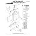
1. CARRY OUT 3D CHECKS. 2. Remove the one (1) screw holding the noise filter to the chassis support. 3. Release the noise filter from the tabs of the fan duct. 4. Disconnect the wire leads from the fan motor. 5. Remove the one (1) screw holding the fan duct to the oven cavity back plate. 6. Remove the fan duct from the oven. 7. Remove the fan blade from the fan motor shaft according to the following procedure. 1) Hold the edge of the rotor of the fan motor by using a pair of groove joint pliers. CAUTION: � Make sure that any pieces do not enter the gap between the rotor and the starter of the fan motor. Because the rotor is easy to be shaven by pliers and metal pieces may be produced. � Do not let the pliers touch the coil of the fan motor because the coil may be cut or damaged. � Do not distort the bracket by touching with the pliers. 2) Remove the fan blade from the shaft of the fan motor by pulling and rotating the fan blade with your hand. 3) Now, the fan blade will be free. CAUTION: � Do not use this removed fan blade again. Because the hole (for shaft) of it may become bigger than a standard one. 8. Now, the fan motor is free.
Shaft
Coil Groove joint pliers
INSTALLATION
1. Install the fan blade to the fan motor shaft according the following procedure. 1) Hold the centre of the bracket which supports the shaft of the fan motor on the flat table. 2) Apply the screw lock tight into the hole (for shaft) of the fan blade. 3) Install the fan blade to the shaft of fan motor by pushing the fan blade with a small, light weight, ball peen hammer or rubber mallet.
CAUTION: � Do not hit the fan blade when installed because the bracket may be deformed. � Make sure that the fan blade rotates smoothly after installation. � Make sure that the axis of the shaft is not slanted. 2. Install the fan duct to the oven cavity back plate with the one (1) screw. 3. Install the noise filter to the fan duct and the chassis support with the one (1) screw. 4. Re-connect the wire leads to the fan motor.
Shaft
Stator Gap Bracket Rotor
Axis Stator Rotor
These are the position where should be pinched with pliers
Table
Center of bracket
Rear view
Side view Figure C-1 Fan motor replacement
R-632 24
|
|
|
> |
|