|
|
|
Who's Online
There currently are 5803 guests online. |
|
Categories
|
|
Information
|
|
Featured Product
|
|
|
 |
|
|
There are currently no product reviews.
 ;
It is an very good and clear scanned service manual.
very recommended.
;
Easy to order the manual. Good quality and fast delivery.
;
The Service Manual for Sansui AU-9500 was very helpfull, in complete and in good printable condition.
Thanks.
;
Dear Sir,
Document is original service document of sharp. I had a problem with the door contacts. Fuses where blown. With the manual in a few minuts is was clear what the problem was.
Manual was of great help.
With kind regards,
Martie Verhoeven
The Netherlands.
 ;
The scan is clear and well readable with very few weaker spots, usually on black background with white letters, but with enough zoom those spots can be read.
Printout is clear, the manual is complete and has all pages scanned.
I would give 5 stars, except that it is not in color, and the schematic and PCB pages are scanned on multiple pages. The document is locked (except printing) so the pages can not be extracted to compose them together for printing on the large plotter
It is worth the price tag.
VL-A111S/H/E/AH131S/H/E VL-AH151S/H/E
4-3. MECHANISM CHECKS AND ADJUSTMENTS
The description given below relates to the general field services, but does not relate to the adjustment and replacement that require high level equipment, jigs, and technical skills. In order to maintain the initial characteristics of the machine, it is necessary to execute the maintenance and check and to prevent damage to tapes and other parts. For adjustments which need jigs, be sure to use the jigs. Notes and cautions (1) For mechanism checks and adjustments, be sure to use the AC adapter as the power supply. (2) For running the tape, be sure to install the cassette control ass�y in advance. (If the cassette control ass�y is to be removed subsequently after its installation.)
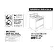
4-3-1. Checking the reel disk height
(1) Remove the cassette control ass�y. (2) Taking due care not to let the master plane touch the tape running areas such as the drum and the guide rollers, position the master plane so that the two guides (A and B in Figure 1) are set in the holes of master plane, then properly set it in the mechanism. (3) Using the slide callipers or the like, check that the distance from the upper surface of master plane to the reel support surface of the S/Tu reel disk is within the specified range. (Figure 2) Note: When measuring, do not apply excessive force to the reel support surface of reel disk. (4) If the measurement is not within the specified range, replace the reel disk ass�y. (5) Check the items (2) to (4) above in the following two modes. a) Standby mode b) Playback (recording) mode
4.4 ± 0.15
B
A
Reel support surface
4.4 ± 0.15
Figure 1
Figure 2
4-3-2. Checking the take-up torque for playback (recording)
(1) Set the torque cassette (JiG8T-012) in position, and check in the SP-mode recording mode (tape recorded in SP mode) that the torque at the tape taking-up side is within the standard range. Standard of take-up torque for SP-mode recording (playback): 9 ± 3 g·cm with ripples less than 4 g·cm (If the torque ripples appear, read the center value of torque between the ripples.)
4-3-3. Checking and adjusting the back tension torque for playback (recording)
(1) Checking Set the torque cassette (JiG8T-012) in position, and check in the SP-mode recording mode (tape recorded in SP mode) that the torque at the tape supply side is within the standard range. Standard of back tension torque for SP-mode recording (playback): 8 ± 2 g·cm with ripples of less than 2 g·cm (Torque ripple must be within 8 ± 2 g·cm) (2) Adjustment If the back tension torque is not within the standard range, adjust the tension spring hooking position. If the back tension is too high, hook the spring in the direction A. If the back tension is too low, hook the spring in the direction B. Note: After back tension torque adjustment be sure to check the tension pole position.
A
B
12
|
|
|
> |
|