|
|
|
Who's Online
There currently are 5756 guests online. |
|
Categories
|
|
Information
|
|
Featured Product
|
|
|
 |
|
|
There are currently no product reviews.
 ;
Great service manual. Unfortunately on page no. 41 there are some details which i can't read.
 ;
Wonderful service... doubt that I could have made the repairs to my turntable without this service manual. Great help!
Well worth the price paid!
;
nice completed SERVICE MANUAL as the description THANK YOU !!!-
;
The service manual is as described and received the link to the download sooner than expected. Great service, quality product. This site is a big help in the electronics repair business.
;
Il service manual molto accurato. Rapidi nella risposta
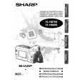
VL-H860S/H/VL-H870S VL-H890S/VL-H94E VL-H96E/VL-H960E
VL-H860S/H/VL-H870S VL-H870U VL-H890S/VL-H94E VL-H875U VL-H96E/VL-H960E VL-H890U Upper flange Lower flange Height setting jig Master plane (JiGMP-MX7U)
4-4-4. Adjusting the Tu guide
After replacement of Tu guide preset and adjust the height. (1) Tu guide height presetting (Figure 6) Adjust the height from the upper surface of mechanism chassis to the upper surface of lower flange with the aid of jig.
Figure 6 (2) Adjusting the Tu guide (Figure 7) 1 Playback the alignment tape (VR2DBOPS). 2 Check that the tape runs at the same height near the capstan shaft in case of V/S F and V/S R. 3 If the tape running position in case of V/S R is higher than the tape running position in case of V/S F, turn clockwise the Tu guide nat. If the tape running position in case of V/S R is lower than the running position in case of V/S F, turn counterclockwise the Tu guide nat.
Capstan shaft Nat
Pinch roller
Figure 7
4-4-5. Checking the V/S F and R waveforms (Figure 8)
(1) Playback alignment tape (VR2DBOPS), and set the V/S R mode. At this time ascertain that the waveform crest pitch is kept constant for more than 5 seconds. (2) Set the V/S F mode. At this time ascertain that the waveform crest pitch is kept constant for more than 5 seconds. Unless the constant pitch is obtained, execute the checks of Section 4-2, 3, and 4.
a
b
c
d
abcd
Figure 8
4-4-6. Checking after adjustment
(1) Envelope check 1 Playback the alignment tape (VR2DBOPS). 2 Ascertain that the envelope maximum to minimum ratio is 65% or more. (Figure 9) 3 Ascertain that the waveform does not change remarkably. (Figure 10)
C A
E MIN E MAX
C
Figure 9 (2) Rise check
E MIN E MAX
Figure 10
65 (%)
C 1/8A
1 Playback the alignment tape (VR2DBOPS). 2 Once eject the cassette, and then load it again. 3 Set the playback mode, and ascertain that the RF waveform rises horizontally within 2 seconds. At this time ascertain that there is no tape slackness near the pinch roller.
Capstan shaft Tu guide
Tape slackness
Tu GR
4 After V/S F, R and FF/REW execute playback, and ascertain that the RF waveform rises horizontally within 2 seconds. At this time ascertain that there is no tape slackness near the pinch roller. Tension pole (3) Checking the tape travel 1 When the tape is played back, ascertain that tape lift and tape curl of 0.3 mm or more do not occur at the lower flange of Si roller, upper flange of Sup GR, upper flange of Tu GR, and upper/lower flange of Tu guide. 2 In case of V/S F and R ascertain that no curl is found at each flange.
Drum Si roller Sup GR Tu GR
Figure 11
Sup tilted pole
Drum
Tu tilted pole
Pinch roller Tu guide
Figure 12
4-4-7. Checking and adjusting the playback switching point
Refer to the description of playback switching point adjustment in section of VCR circuit adjustment.
4-6
|
|
|
> |
|