|
|
|
Who's Online
There currently are 6043 guests online. |
|
Categories
|
|
Information
|
|
Featured Product
|
|
|
 |
|
|
There are currently no product reviews.
 ;
Probably it never existed a 1081 official service manual from Commodore, it's look more like a NAPCEC service manual & diagrams compilation of the 1084 series and his variants, like the nap6523, 8cm505, 1084S, 1084P and obviously the 1081. It's more complete than other scans and the quality of the scans also are far superior. It has two circuit diagrams variants of the 1081, mono and stereo versions. It doesn't include a diagram for the Philips CM8500 or CM8501, they look like the 1081 but they are slightly different.
 ;
Rapid, clear well done as all the scheme I downloaded from this site. Great job very functional and very useful
;
Great copy of the manual, has all information required for servicing,
;
I work at an authorized service center and I can tell if a manual is as it should be. This one is. It may be a scan, but a very good one at that. The interesting part for me was the curcuit diagram which was scanned at high quality, making it as good as the original. I will definitely be back as a customer. I need not say this, but I will: the price was the best. Thank you owner-manuals.com .
;
really a very good manual even sometimes the quality is no so good as before still very readible and very very useful!
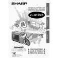
VL-MC500S/H/E
3. DISASSEMBLY OF THE SET
Note: Before removing the cabinet, turn off the power supply, and ascertain that the battery have been removed. 1. 3.
LCD Panel
(d)
(c) Battery Unit (d)
FPC
(d)
1) 2) 3) 4)
Detach the battery unit. Remove the three screws ((d)XiPSN17P03000). Remove the one screw ((c)LX-HZ0050TAFN). Detach the LCD cabinet in the direction of the arrow.
1) Remove the FPC of the LCD panel, and detach the LCD panel in the direction of the arrow.
4.
(d) (d) (d)
2.
(d)
Tillt FPC
(d)
(d)
connector Main PWB
(d) Speaker Wire Connect (d)
Inverter PWB
1) Remove the two screws ((d)XiPSN17P03000). 2) Disconnect the speaker wire connector. 3) Detach the side cover in the direction of the arrow.
(d)
FPC
1) Remove the four screws ((d)XiPSN17P03000), the tilt FPC and the tilt wire connector to detach the lens section. 2) Remove the two screws ((d)XiPSN17P03000) to detach the main PWB. 3) Remove the one screw ((d)XiPSN17P03000) and the FPC to detach the inverter PWB.
4
|
|
|
> |
|