|
|
|
Who's Online
There currently are 5507 guests online. |
|
Categories
|
|
Information
|
|
Featured Product
|
|
|
 |
|
|
There are currently no product reviews.
 ;
The service manual was very usable and clear enough to see the individual values of all of the components (unlike some of the service manuals I have gotten in the past from web sites similar to this one). The price was right and the information was greatly appreciated. It helped me with an otherwise very difficult repair. It was much needed and appreciated. A faster turn around on my order would be nice, but I understand the constraints on your staff's time. Thank you for your service.
 ;
Excellent manual. Helped me out with disassembling and troubleshooting my projector.
;
thanks you are the best.Very good detail, Quick service response. A useful service manual with all details.
;
Great service!!! Polecam gorąco wszystkim zainteresowanym
;
I liked the price plus it had everything i needed to service the tv.
thankyou Tim Hertz
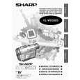
VL-WD250S/H/E VL-WD450S/H/E
3. DISASSEMBLY OF THE SET
Note: Before removing the cabinet, turn off the power supply, and ascertain that the battery have been removed. 1.
(d)
Turn SW connector LCD FPC 1, 2
3.
(d)
(e)
Joint main FPC
(b) (d)
(b) (c)
1) Disconnect the connector of the turn SW. 2) Remove the joint main FPC. 3) Remove the LCD FPCs (2 sheets), and lift up the cabinet B ass'y.
4.
1) Remove the screws ((c)XiPSF17P04000)(5 pcs.) and ((b)LXHZ0063TAFF)(1 pc.) on the bottom cover to remove the bottom cover. 2) The screws ((d)XiPSN17P04000)(2 pcs.), ((b)LX-HZ0063TAFF)(1 pc.) and ((e)LX-HZ0063TAFN)(1 pc.) on the front cover, and open the front cover. Then disconnect the connector of the microphone. 3) Remove the screws ((d)XiPSN17P04000)(3 pcs.) fixing the shoe angle to remove the shoe angle. Remove the connector of the zoom microphone which is located in the front, and then slide the top side cover forward and lift it up to remove it.
(b)
Operation PWB connector
2.
(d)
(b) (b)
(b)
1) Remove the screws ((b)LX-HZ0063TAFF)(5 pcs.) to remove the joint PWB. 2) Disconnect the connector of the operation PWB. 3) Remove the screws ((b)LX-HZ0063TAFF)(3 pcs.) to remove the operation PWB.
(d)
5.
(d)
(c) (b)
(d)
1) Turn the V/F, and then remove the screws ((b)LX-HZ0063TAFF)(7 pcs.) and ((c)XiPSF17P04000)(1 pc.) fixing the battery cover. Disconnect the connector of the battery terminal on the bottom. 2) Remove the screws ((d)XiPSN17P04000)(4 pcs.) on the top side and the screw ((d)XiPSN17P04000)(1 pc.) on the side. 1) Disconnect the connectors (2 pcs.) of the lens, remove the screw ((d)XiPSN17P04000)(1 pc.), and lift it up. 2) Disconnect the connector of the V/F, remove the screw ((d) XiPSN17P04000)(1 pc.), and lift up the V/F unit to remove it.
4
|
|
|
> |
|