|
|
|
Who's Online
There currently are 5821 guests online. |
|
Categories
|
|
Information
|
|
Featured Product
|
|
|
 |
|
|
There are currently no product reviews.
 ;
Exellent manual ,it was in great condition,and got all the info i expected,5 stars!!
;
I searched the Internet exhaustively for this manual and Owner-Manuals was the least expensive...but provided an excellent reproduction within 4 hours. Very satisified.
 ;
Rapid and precise delivery. Good print. On the spot.
;
available for me the service manual is in order!
thanks
;
This is exactly the thing you need to service this box. The manual is complete and the quality of the scan is good. I recommend this!
VL-WD650S/E
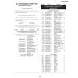
3. DISASSEMBLY OF THE SET
Note: Before removing the cabinet, turn off the power supply, and ascertain that the battery have been removed. 1.
(d)
Turn SW connector LCD FPC 1, 2
3.
(d)
(e)
Joint main FPC
(b) (d)
(b) (c)
1) Disconnect the connector of the turn SW. 2) Remove the joint main FPC. 3) Remove the LCD FPCs (2 sheets), and lift up the cabinet B ass'y.
4.
1) Remove the screws ((c)XiPSF17P04000)(5 pcs.) and ((b)LXHZ0063TAFF)(1 pc.) on the bottom cover to remove the bottom cover. 2) The screws ((d)XiPSN17P04000)(2 pcs.), ((b)LX-HZ0063TAFF)(1 pc.) and ((e)LX-HZ0063TAFN)(1 pc.) on the front cover, and open the front cover. Then disconnect the connector of the microphone. 3) Remove the screws ((d)XiPSN17P04000)(3 pcs.) fixing the shoe angle to remove the shoe angle. Remove the connector of the zoom microphone which is located in the front, and then slide the top side cover forward and lift it up to remove it.
(b)
Operation PWB connector
2.
(d)
(b) (b)
(b)
1) Remove the screws ((b)LX-HZ0063TAFF)(5 pcs.) to remove the joint PWB. 2) Disconnect the connector of the operation PWB. 3) Remove the screws ((b)LX-HZ0063TAFF)(3 pcs.) to remove the operation PWB.
(d)
5.
(d)
(c) (b)
(d)
1) Turn the V/F, and then remove the screws ((b)LX-HZ0063TAFF)(7 pcs.) and ((c)XiPSF17P04000)(1 pc.) fixing the battery cover. Disconnect the connector of the battery terminal on the bottom. 2) Remove the screws ((d)XiPSN17P04000)(4 pcs.) on the top side and the screw ((d)XiPSN17P04000)(1 pc.) on the side. 1) Disconnect the connectors (2 pcs.) of the lens, remove the screw ((d)XiPSN17P04000)(1 pc.), and lift it up. 2) Disconnect the connector of the V/F, remove the screw ((d) XiPSN17P04000)(1 pc.), and lift up the V/F unit to remove it.
4
|
|
|
> |
|