|
|
|
Who's Online
There currently are 5728 guests online. |
|
Categories
|
|
Information
|
|
Featured Product
|
|
|
 |
|
|
There are currently no product reviews.
 ;
Superb rendition. Drawings (schematics) complete and unabridged. I do a great deal of vintage audio restoration. Documentation is essential for successful repairs. I have found sources over the years that offer good documentation, but rarely all that is necessary. Owner's Manuals has filled that void with complete and legible documentation. They have narrowed my "favorites" to a more manageable collection. This Denon manual in particular contained the latest revisions level, and offered alterations favorable to updating the item. The Illustrated Parts Breakdown (IPB) was well enough detailed to simplify part symbols and physical locations. You will not be disappointed!
;
Clear and concise. Saved me a lot of time and money.
;
Superb manual. Exactly what I ordered and made available in a very timely manner.
 ;
very fast detailed and accurate hope to do business again
;
This was precisely what I was looking for. Complete and good quality!
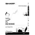
XG-NV6XE
ADJUSTING THE PC INTERFACE (CPCi-0035CE02. PC I/F Unit)
1. Setting the oscilloscope
Set the range to DC 1 V/div and 5µ/div.
2. Connecting the PC Interface
1) 2) 3) 4) 5) Fit the PC I/F in position and make sure the CON2, CON3 and CON4 connectors are all tight in place. Connect the cable between the ANALOG OUTPUT (PC computer) and the DSUB connector (INPUT1 of the proejctor). Set the projector�s input selector to the INPUT1 position. Make sure the Dsub/BNC selector is at the Dsub position. Set the PC computer in the XGA mode (1024 x 768, 60 Hz, 32-step scale). Adjust the output amplitude to 700 mVp-p (terminated with 75 ohms) for the black-to-white portions. Turn on the power.
3. Adjusting and checking the level
1) 2) 3) 4) 5) 6) Press the S5001 switch to go to the process mode. Set the SH-PHASE on the OUTPUT3 menu to 8. (Make the characters on screen clear and crisp.) Connect the oscilloscope to TP2 and adjust the M-BRIGHT data of OUPUT2 so that the signal�s black level be 1.9 V. Adjust the R-BRIGHT data of A/D so that the black level of the signal at TP1 be 1.9 V. Adjust the B-BRIGHT data of A/D so that the black level of the signal at TP2 be 1.9 V. Make sure the GAIN data on the A/D menu is 155.
4. Adjusting the DTV
1) 2) 3) 4) 5) 6) Set the switch to the BNC input terminal of INPUT1 Select the signal type of the user menu option for the component. Feed the Y signal of 480P to the G(Y) input terminal. Keep the R(Pr) and B(Pb) signals off. Connect the voltmeter to TP1, and adjust the DTV�s B-BRIGHT data to 2.65±0.02 V. Connect the voltmeter to TP3, and adjust the DTV�s R-BRIGHT data to 2.65±0.02 V. Finally press the S5001 switch again to quit the process mode.
32
|
|
|
> |
|