|
|
|
Who's Online
There currently are 5861 guests online. |
|
Categories
|
|
Information
|
|
Featured Product
|
|
|
 |
|
|
There are currently no product reviews.
 ;
The Service Manual for Sansui AU-9500 was very helpfull, in complete and in good printable condition.
Thanks.
;
Dear Sir,
Document is original service document of sharp. I had a problem with the door contacts. Fuses where blown. With the manual in a few minuts is was clear what the problem was.
Manual was of great help.
With kind regards,
Martie Verhoeven
The Netherlands.
 ;
The scan is clear and well readable with very few weaker spots, usually on black background with white letters, but with enough zoom those spots can be read.
Printout is clear, the manual is complete and has all pages scanned.
I would give 5 stars, except that it is not in color, and the schematic and PCB pages are scanned on multiple pages. The document is locked (except printing) so the pages can not be extracted to compose them together for printing on the large plotter
It is worth the price tag.
;
let's say first that i do not need to have a credit for my opinion, i am a retired sparkie and i voluteerd to fix an electronic device for a local "Youthgroup",as no diagram was present i checked the "net" and gambled on this site and paying some fee via PayPall, i was gladly surprised that the manual arrived as was stated, GOOD SHOW, and best wishes, John
;
I had been looking for a Manual for my CS2150 for quite a while -- in fact I had just about given up. I saw this site and decided to download the Manual. When I Received it by Email I was really pleased with what I got, with the result that My Kenwood 'Scope is now 100% repaired and working well. As an AV Serviceman, you need a good 'scope, and thanks to this site, and the Service Manual, I have been able to repair it. The Manual was a copy of the Factory Original and the copy was very clear, especially in the area of the Circuit Schematics, where You really need to be sure of what You are looking at.
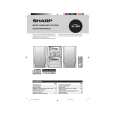
XL-30H/30W
� HF error.
Is output (tracking error signal) obtained at the pins 46 (TEI) and 47 (TEZI) of IC802 the CD TEST MODE "STEP 4" is changed to "STEP 5"? Yes
test mode "step 4" test mode "step 5"
No
Is output obtained at the pins 2 and 5 of BI802/CNS802 No
Optical pickup failure.
Yes Check the periphery of IC801. Check the PWB pattern between pin 12. (TEO) of IC801 and pins 46 and 47 of IC802. Is it normal ? Yes Check the PWB pattern between pin 50 (TEO) of IC802 and pin 18 of IC804. Check the periphery of IC804 and BI801/CNS801. If OK. Optical pickup failure. IC801 is faulty. No
TEI TEZI
Is output (HF signal) obtained at the pin 38 (RFI) of IC802 when the CD TEST MODE "STEP 4" is changed to "STEP 5"? Yes
test mode "step 4" test mode "step 5"
No
Is output obtained at the pins 1 and 3, 4 of BI802/CNS802. No Yes Check the periphery of IC801.
Optical pickup failure.
RFI
Check the PWB pattern between pin 19 (RFGO) of IC801 and pins 38 (RFI) of IC802. If OK. IC801 is faulty
Is output (HF signal) obtained at the pins 41 (RFZI) and 42 (RFRP) of IC802 when the CD TEST MODE "STEP 4" is changed to "STEP 5"? Yes
RFZI RFRP test mode "step 4" test mode "step 5"
No
Check the periphery of IC801. Check the PWB pattern between pin17 (RFRP) of IC801 and pins 41 (RFZI) and 42 (RFRP) of IC802. If OK. IC801 is faulty.
Is the following wave output to the pin 55 (DMO) of IC802 when the CD TEST MODE "STEP 4" or "STEP 5"? Yes
DMO test mode "step 4" test mode "step 5"
No
Check the periphery pins 28~32 of IC802. If OK. IC802 failure.
Normal.
� No sound.
No sound from both L and R-ch? No Yes Check the interval between the pins 82 or 85 of IC802 and the pins 1 or 3 IC601.
Is +4.5V applied to pin 83 (DVDD) of IC802? Yes No
Check the PWB pattern between R819 and Q861.
Is signal of pins 82 and 85 of IC802 output? Yes The main PWB is faulty. No
Check the peripheral parts of IC802. If OK, IC802 is faulty.
� 42 �
 $4.99 XL-30H SHARP
Owner's Manual Complete owner's manual in digital format. The manual will be available for download as PDF file aft…
|
|
|
> |
|