|
|
|
Who's Online
There currently are 6011 guests online. |
|
Categories
|
|
Information
|
|
Featured Product
|
|
|
 |
|
|
There are currently no product reviews.
 ;
It is wonderful done!!! a great job in scanning the manual. Superior quality in all the electric scheme. Very understandable and net!!! Thank you!
 ;
muy buen manual por lo completo de este algunos esquemas estan muy divididos lo que hace algo dificil el seguimiento.
;
very good manual, with detail and clarity in esquematic diagrams and waveforms .
;
Very quality copy of original service manual, which contains the circuit diagrams, PCB and lists of components, well as recommendation for calibration procedures of device, also everything else, that need for repair, tuning and use this oscilloscope.
All presented copies have high-resolution, so you can view all in detail.
This manual will very useful for simple owners and for repairers.
I recommend these manual, because myself is owner of Philips PM3216 and I need sometimes servicing these oscilloscope (principally calibrating).
Also, these document is an example of excellent design of technical documentation.
;
Excellent printing quality.
A complete and very usefull service manual with all details.
GREAT SERVICE AT VERY LOW PRICE!
A+++++++++++++++++++++++++
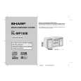
XL-MP150H/MP150E
2. CD-MECHANISMUS
Führen Sie zum Ausbau des CD-Mechanismus die Schritte 1 bis 3, 14, 15 des Demontagevorgangs aus (siehe Seiten 3-3, 3-4).
Sicherungsscheibe (A3) x1 Optischer Abnehmer CDMechanismus (A1) x2 ø2.6 x5mm
2.1. Optischen Abnehmer ausbauen (siehe Abb. 1)
1. Die beiden Schrauben (A1) lösen und die Welle (A2) abnehmen. 2. Sicherungsring (A3) und Zahnrad (A4) entfernen. 3. Optischen Abnehmer abnehmen. HINWEIS:U m w ickeln S ie nach d em E ntfernen des A nschlusse s für de n o ptischen A b nehm er da s vo rd ere E nde des A nsch lusses m it leitfähiger A lu m in ium folie, um d en o ptischen A bn ehm er vo r e lektrostatische r A ufladu ng zu schützen.
2.2. CD herausnehmen (siehe Abb. 2~6)
1. Wenn sich die CD in der Wiedergabeposition befindet, drehen Sie das in Abb. 2 dargestellte Untersetzungszahnrad C, bis sich das CD-Fach in der Position �STOCK� befindet. Drehen Sie es dann weiter, um das CD-Fach (Abb. 6) auszufahren, so dass die CD aus dem Fach genommen werden kann. 2. Wenn sich der CD-Mechanismus beispielsweise in der Wiedergabeposition für Fach Nr. 1 befindet und die in Fach Nr. 3 befindliche CD entnommen werden soll, gehen Sie wie folgt vor: Wenn sich die Senk-/Hebeplatte in der Position für Fach Nr. 1 befindet, drehen Sie das Untersetzungszahnrad C im Uhrzeigersinn, bis sich das CD-Fach in der Position �STOCK� befindet. Drehen Sie das Untersetzungszahnrad D im Uhrzeigersinn (Abb. 3), um den CD-Mechanismus in die Position für Fach Nr. 3 zu bewegen. Dies kann anhand der Position der Senk-/Hebeplattebasis zur auf dem Hauptgehäuse gezeigten Markierung überprüft werden (s. Abb. 4). � Der Wechsler ist normalerweise durch die obere Platte abgedeckt. Zur besseren Veranschaulichung ist die obere Platte nicht dargestellt. (Abb. 5, 6)
CD Disc-Fach Führungsfach
Antrieb (A4) x1
Welle (A2) x1
Abb. 1
Untersetzungsrad C
Vorne
Hinten
Abb. 2
Untersetzungsrad D
Auf
Ab
Abb. 3
CD in Position 'PLAY'. CD Disc
Senk-/Hebeplatte
CD in Position 'STOCK'.
Abb. 5
CD
Markierung 1 Markierung 3 Markierung 5 (DISC 1) (DISC 3) (DISC 5) Markierung 2 Markierung 4 (DISC 2) (DISC 4)
CD aus Fach nehmen. Fach öffnen
Abb. 4 Abb. 6
3�2
|
|
|
> |
|