|
|
|
Who's Online
There currently are 5947 guests online. |
|
Categories
|
|
Information
|
|
Featured Product
|
|
|
 |
|
|
There are currently no product reviews.
 ;
I downloaded the document. The manual was complete, well scanned and everything was legible. I could zoom in see what I needed to know. There's not much more that you can ask.
;
It was complete service manual with all needed service informations. Thanks.
 ;
El manual esta muy detallado, los numeros de partes y los esquemas de despiece son correctísimos y muy claros, tanto para los técnicos experimentados como para los novatos.
;
Ottima qualità grafica e completo nelle notizie. Costo abbastanza contenuto.
;
Great and quick support. The maual was exactly what I was looking for and my problem
solved. Many thanks.
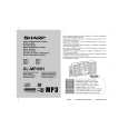
XL-MP45H
SERVICE MANUAL
No. SY379XLMP45H/
MICRO COMPONENT SYSTEM
MODEL
XL-MP45H
XL- MP45H Micro Component System consisting of XL- MP45H (main unit) and CP- XL45H (speaker system).
� In the interests of user-safety the set should be restored to its original condition and only parts identical to those specified should be used.
� Note for users in U.K. Recording and playback of any material may require consent, which SHARP is unable to give. Please refer particularly to the provisions of Copyright Act 1956, the Dramatic and Musical Performers Protection Act 1956, the Performers Protection Acts 1963 and 1972 and to any subsequent statutory enactments and orders. This Service Manual is for the XL-MP45H, which is a minor modification model of the XL-MP35H. This Service Manual, therefore, describes only the changed points from the Service Manual. Please refer to the XL-MP35H Service Manual (SY378XLMP35H/) together with this Service Manual. This speaker CP-XL45H is available in assembles only and may not be disassembled.
CONTENTS
Page
SAFETY PRECAUTION FOR SERVICE MANUAL .......................................................................................................... 2 SPECIFICATIONS ............................................................................................................................................................ 3 NAMES OF PARTS .......................................................................................................................................................... 4 DISASSEMBLY ................................................................................................................................................................. 5 ADJUSTMENT .................................................................................................................................................................. 7 NOTES ON SCHEMATIC DIAGRAM ............................................................................................................................... 8 TYPES OF TRANSISTOR AND LED ................................................................................................................................ 8 WAVEFORMS OF CD CIRCUIT ....................................................................................................................................... 9 BLOCK DIAGRAM .......................................................................................................................................................... 10 SCHEMATIC DIAGRAM ................................................................................................................................................. 15 WIRING SIDE OF P.W.BOARD ...................................................................................................................................... 24 PARTS GUIDE/EXPLODED VIEW
SHARP CORPORATION
�1�
This document has been published to be used for after sales service only. The contents are subject to change without notice.
|
|
|
> |
|